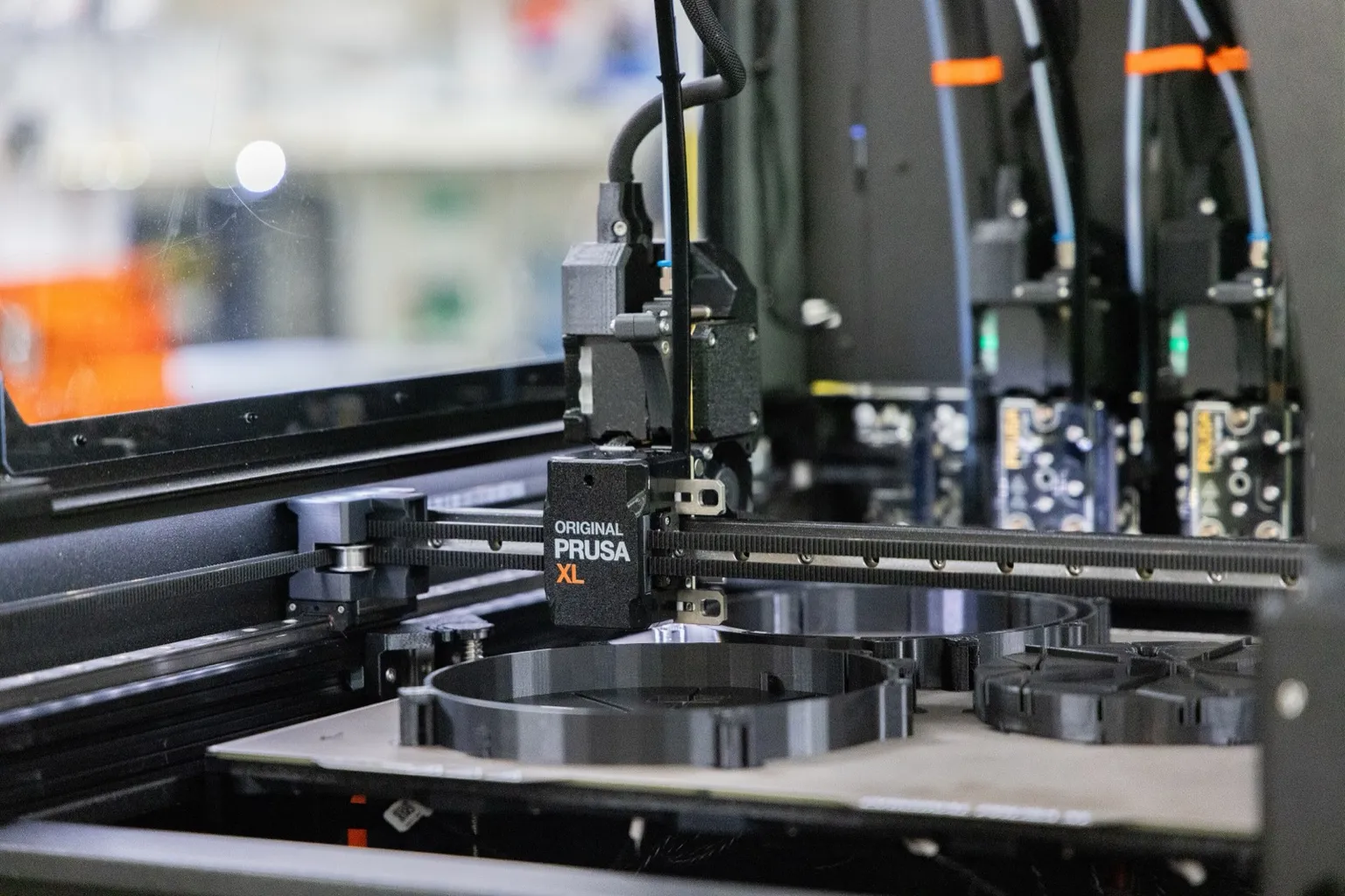
Every tool on a toolchanger has its own nozzle, and no two sit in exactly the same place once picked up. Offset calibration measures each nozzle against the first tool; dock calibration is a separate job that teaches the printer where to pick each tool up.
Make the first tool the reference with zero offsets, then measure every other nozzle’s X, Y and Z distance from it. The Prusa XL and Snapmaker U1 have a built-in calibration for this. On a Klipper toolchanger such as a StealthChanger, you set Z with a paper test or probe and measure XY with a contact probe or a nozzle camera.
Calibrate the docks first, then pick tool 1 (T0) as the reference with all offsets at zero. Measure every other tool’s X, Y and Z difference from it. A Prusa XL does this from Control > Calibrations & Tests > Tool Offset Calibration, a Snapmaker U1 from Settings > Device Calibration. Klipper builds use a probe or camera.
On every platform:
- Clean nozzles first. Snapmaker says filament stuck to a nozzle changes its trigger height. The klipper-toolchanger docs say calibration is only as accurate as your nozzles are clean.
- Recalibrate after hardware changes: a nozzle or hotend swap, a crash, or a move. Prusa’s XL nozzle-replacement guide ends with Tool Offset Calibration, and Snapmaker lists moving the U1 and replacing a toolhead or hotend.
On a printer with two fixed nozzles rather than swappable tools, see nozzle offset calibration on a dual nozzle printer.
A tool docking calibration teaches the printer where each dock is, so the carriage can drive in, lock onto a parked tool and park it again without a crash. It locates the docks, not the nozzles. Tool offset calibration then measures where each picked-up nozzle sits relative to the first tool. Prusa’s setup wizard does the docks first.
| Printer |
Name in the docs |
How it is done |
Where the result lives |
| Prusa XL |
Dock Position Calibration |
A screen wizard, one dock at a time, with screws and dock pins |
Printer memory |
| Snapmaker U1 |
Pick & park coordinates |
X from Homing calibration; Y jogged by hand in Fluidd |
extruder_config.json |
| StealthChanger (Klipper) |
Dock parking |
Jog into each docked tool and record M114 |
params_park_x/y/z in each [tool Tn] |
Prusa XL. Start it from Control > Calibrations & Tests > Dock Position Calibration. For each dock, the wizard has you:
- remove both dock pins with the mini wrench
- loosen the two dock screws a few turns
- move the tool changing mechanism to the tool by hand and lock the metal bars
- tighten the upper screw, then clear the space while the printer pulls the tool out
- tighten the lower screw
- refit the pins so the printer can make a few test moves
Error #17103 (dock position out of bounds) has a two-part fix from Prusa. Check that the metal profile holding the docks sits all the way to the left, seen from the back. Then tighten the docks with the long end of the 2.5 mm Allen key until they have no play, and rerun the calibration.
StealthChanger. The wiki’s procedure, per tool:
- With a tool on the shuttle, home and level, then place the tool in its dock.
- Jog the gantry in as if picking the tool up, until the light on the OptoTap PCB changes.
- Raise Z by 1 mm, run
M114 and save X, Y and Z to params_park_x, params_park_y and params_park_z.
- Test with
TEST_TOOL_DOCKING RESTORE_AXIS=XYZ. The wiki sets params_path_speed to 300 for this test, then resets it.
Set params_close_y to the highest params_park_y plus 30. params_safe_y is params_close_y plus your thickest tool plus 10.
Snapmaker U1. Run Homing calibration from Settings > Maintenance to set X. Y needs Advanced Mode and Fluidd: pick the tool with its T0 to T3 macro, then jog until the toolhead’s side pin lines up with the parking bracket’s docking slot. Check the value by sliding the tool into the dock with G91 then G1 X-8.5 F3600 (toolhead 1) or G1 X8.5 F3600 (toolheads 2 to 4). If a toolhead falls off, Snapmaker says its Y value is too small.
A tool that will not pick up or park has a dock problem, not an offset problem. See failed tool pickups.
These steps follow the StealthChanger wiki and use viesturz’s klipper-toolchanger (see Klipper toolchanger config). On a StealthChanger each tool carries its own Z probe.
- Break in the probes. Heat soak the machine and run
PROBE_ACCURACY SAMPLES=100 a couple of times on each tool.
- Set each tool’s probe Z offset. Put the tool on the shuttle, run
INITIALIZE_TOOLCHANGER, G28, QUAD_GANTRY_LEVEL, G28. Do a cold paper test and save the result as z_offset in that tool’s [tool_probe Tn]. Repeat for every tool, then FIRMWARE_RESTART.
- Set gcode_z_offset per tool. Home and level with T0 only, then
G1 Z10 F600. Swap the next tool onto the shuttle by hand. Paper-test it, run M114 and copy Z into gcode_z_offset in [tool Tn]. T0’s value is always 0.
- Calibrate the docks. Record each tool’s park position so automatic tool changes work during XY calibration.
- Clean every nozzle. Remove all plastic from the tips; a blob shifts what a probe or camera sees.
- Measure XY against T0. Use a contact probe (Sexball/NozzleAlign or Nudge) or a nozzle camera (kTAMV or Axiscope). T0’s
gcode_x_offset and gcode_y_offset stay at 0.
- Save the offsets. Put each result in
gcode_x_offset and gcode_y_offset under [tool Tn]. With a contact probe, the example macro saves them for you with SET_TOOL_PARAMETER and SAVE_TOOL_PARAMETER.
- Restart and test. Run
FIRMWARE_RESTART, then print a multi-tool test part and check the color boundaries.
Klipper-toolchanger keeps tool offsets separate from your own G-code offsets, so a Z baby-step made in Mainsail or Fluidd survives tool changes.
A contact probe is a small switch mounted beside the bed. Each nozzle bumps it from several directions to find the nozzle’s center.
- Sexball probe. The StealthChanger parts list describes it as a sexbolt-style probe with its shaft replaced by a 12 mm ball on an M5 threaded pin. The wiki says to use hartk-style bodies with sleeves because knockoffs have too much slop.
- NozzleAlign (viesturz) has printable ball and rail probe designs, quoted as repeatable to about 0.01 mm.
- Nudge (zruncho3d) breaks an electrical path when the nozzle pushes its tip. Its README example shows a 0.0010 mm standard deviation over ten X samples and says Z repeats less well than XY.
The software side is [tools_calibrate] in klipper-toolchanger. Park T0 roughly over the probe (it finds the center within 1 to 2 mm) and run TOOL_LOCATE_SENSOR. Then run TOOL_CALIBRATE_TOOL_OFFSET on each other tool. The project’s CALIBRATE_TOOL_OFFSETS example macro heats the bed to 95 °C and each hotend to 150 °C, then loops through the tools and saves X, Y and Z from the probe.
Its docs suggest 0.05 mm for samples_tolerance on a good probe. A Nudge probe is wired normally closed and a microswitch-type Sexball normally open, so the pin: inversion differs. TOOL_CALIBRATE_PROBE_OFFSET measures the Z gap between where the nozzle touches the probe and where the tool’s own bed probe triggers.
Nozzle camera: kTAMV or Axiscope
A StealthChanger nozzle cam is an upward-facing camera under the nozzle path. You center each nozzle over it and read the XY difference from T0 with one of two Klipper tools:
- kTAMV finds the nozzle with OpenCV. Run
KTAMV_CALIB_CAMERA, KTAMV_FIND_NOZZLE_CENTER and KTAMV_SET_ORIGIN with T0. Then, for each tool, run KTAMV_FIND_NOZZLE_CENTER and KTAMV_GET_OFFSET. It measures X and Y only. Its GitHub repository was last updated in April 2024.
- Axiscope is a web page (port 3000) where you line each nozzle up on a crosshair by eye. Capture T0, switch tools and realign; it calculates the offset. It needs klipper-toolchanger, and the camera can be a DIY OV9726 build or a pre-assembled unit. An endstop switch adds optional Z calibration. Don’t load the toolchanger’s
calibrate_offsets.cfg alongside it: both define probe_multi_axis, which makes Klipper stop with an error. Its repository was updated in August 2026.
The original multi-tool XL measures each tool against a calibration pin screwed into the bed. The toolhead’s load cell senses contact. Unload filament from every tool first.
- Prepare the pin. Push the calibration pin into its plastic key so a small gap is left on top.
- Start the calibration. Go to Control > Calibrations & Tests > Tool Offset Calibration and press Continue.
- Fit the sheet. Put the print sheet on the heatbed when asked; the printer runs a short calibration.
- Install the pin. Remove the sheet and screw the pin clockwise into the middle of the heatbed. The printer then calibrates every tool head.
- Remove the pin. Unscrew it counterclockwise, put the sheet back and let the printer finish.
- Store the pin. Prusa’s guide puts it back in the side filament sensor.
If it fails with error #17107 (pin not reached), check that the pin is installed. Prusa’s fixes for error #17104 (tool offset out of bounds) are, in order:
- unload filament
- tighten the nozzle set screw with a TX8 key, holding it at 35 to 40° to spare the hotend cables
- clean the nozzle at 250 °C with a brass brush
- swap in a hotend from a tool that passes
- recalibrate that tool’s dock
- stop vibration near the printer, such as a neighboring printer
Fine-tune by print. Prusa suggests its Multi-tool manual calibration after a nozzle crash or with custom nozzles. Print its test model from Printables in PLA on a Satin sheet, in contrasting colors that are not dark. For each tool pair, find the best-aligned marks: the largest mark is 0 and medium marks are 0.5 mm. Add those values to the existing offsets in LCD Menu > Settings > Tool > Tool #; tool 1 stays at zero.
Prusa XL+. The XL+ swaps the pin for a dedicated electronic sensor. Prusa says calibration is fully automatic and about twenty times faster. See the Prusa XL as a toolchanger.
Snapmaker says the U1 calibrates the XYZ offsets between its four toolheads to within 0.04 mm, measured with clean nozzles.
- Update and unload. Install the latest firmware and unload filament from the toolheads.
- Level the bed. Run Settings > Maintenance > Manual Leveling. Then go to Settings > Device Calibration, turn on Heated Bed Leveling and press Start.
- Clean the nozzles. Heat any nozzle with residue to its filament temperature and remove it with tweezers or a wire brush.
- Check the hotends. Tighten a loose hotend’s two screws with an H2.0 hex key. The gap between the hotend’s copper plate and the calibration sensor should be 0.1 to 0.4 mm (about a sheet of A4 paper).
- Run the calibration. Go to Settings > Device Calibration > Multi-toolhead Offset Calibration and follow the screen.
- Check with a print. Print a four-color test model. Colors should meet with no gaps or overlap.
If colors still miss, clean the steel balls and pogo pins with alcohol and regrease the balls with the white lithium grease from the tool kit. Snapmaker says dry steel balls cause positioning errors. For the machine itself, see the Snapmaker U1.