How a 3D printer toolchanger works
How to slice a model for a toolchanger printer
A toolchanger needs a slicer profile with one extruder per toolhead, a start G-code that names the first tool, and settings that keep parked tools from oozing. Here are the settings for the Prusa XL in PrusaSlicer, a StealthChanger or other Klipper toolchanger in OrcaSlicer, and the Snapmaker U1 in Snapmaker Orca.
Published · Last verified
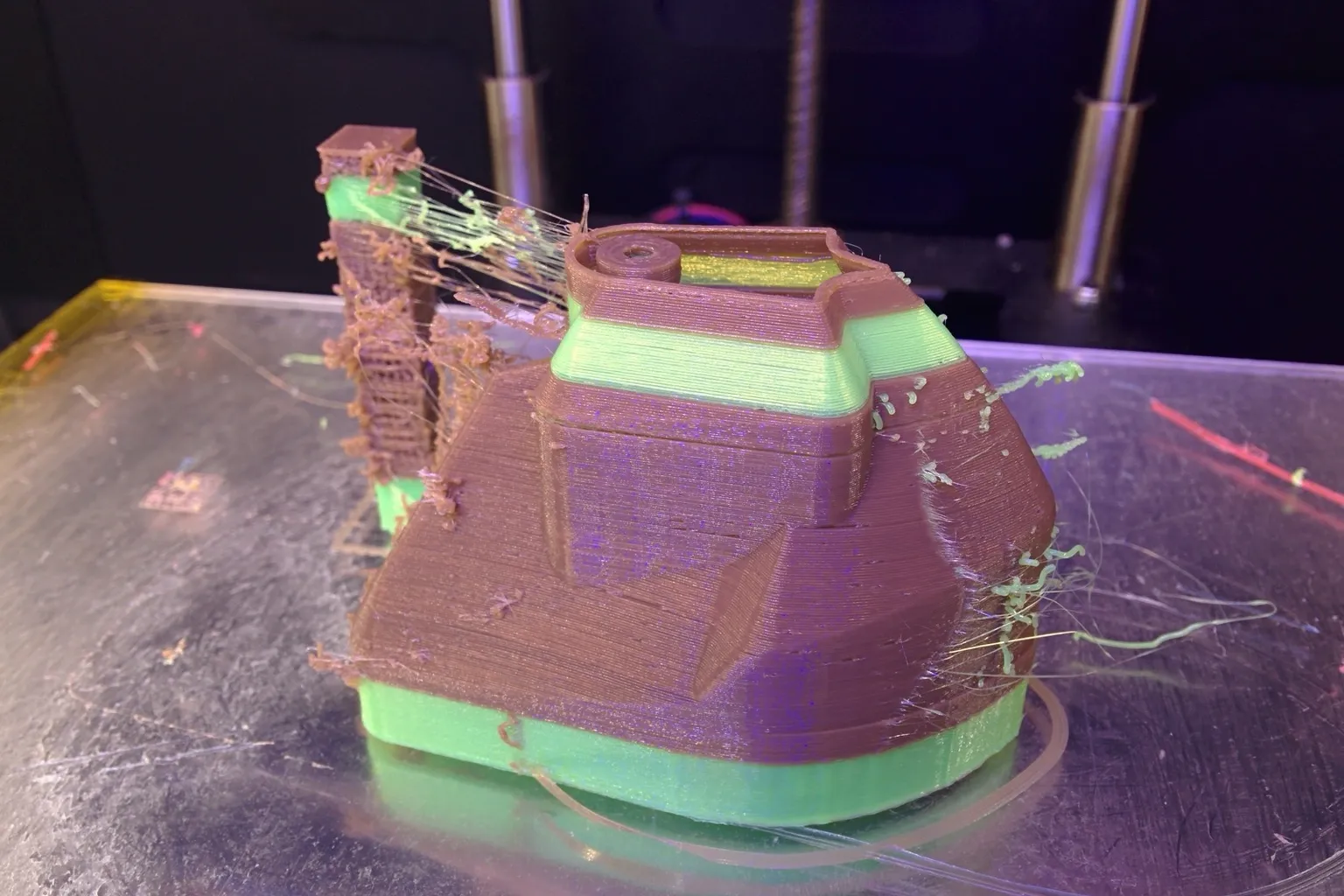
To slice for a toolchanger, give the printer profile one extruder per toolhead, assign a tool to every part, and keep ooze prevention and a prime tower on.
How do you slice a model for a toolchanger printer?
Use a printer profile with one extruder per toolhead, load one filament per extruder, and assign each part, painted region or feature to a tool. Keep ooze prevention on so parked tools drop to a standby temperature, and print a prime tower. On Klipper toolchangers, the start G-code sends PRINT_START the first tool and every tool’s temperature.
Which slicer you use depends on the machine:
| Printer | Slicer | Printer profile |
|---|---|---|
| Prusa XL (multi-tool) | PrusaSlicer | Prusa’s XL multi-tool profiles from the Configuration Wizard |
| Snapmaker U1 | Snapmaker Orca, Snapmaker’s fork of OrcaSlicer | Snapmaker’s U1 profile |
| StealthChanger and other klipper-toolchanger builds | OrcaSlicer 2.2 or later, PrusaSlicer, SuperSlicer, Cura 5.8 or later | Your own multi-extruder profile |
Tool assignment works as on a two-nozzle printer; assigning filaments to nozzles covers it in Cura too.
How to slice for the Prusa XL in PrusaSlicer
- Pick the multi-tool profile. In Configuration > Configuration Wizard > Prusa Research, select the XL multi-tool printer that matches your tool count and nozzle size.
- Load a filament for each tool. The right panel has one filament box per extruder; its color square changes only the preview color.
- Assign tools to parts. In Advanced or Expert mode, double-click the colored box next to a part in the object list, press the tool’s number key, or right-click the part and choose Change extruder. For a single-body model, assign tools with the painting tool.
- Assign tools to features if needed. Print Settings > Multiple Extruders sets separate extruders for perimeters, infill, solid infill, support material/raft/skirt and support interface.
- Pick a wipe tower extruder. In the same section, set Wipe tower extruder to one tool. At 0, the tower uses whichever tool printed last, and Prusa warns that different filaments may not stick to each other there, which can break the tower and cause a crash. For a tall tower, raise the Stabilization cone apex angle (0 to 90 degrees; a larger angle gives a wider base).
- Leave Ooze prevention on. Each parked tool then drops to the Idle temperature in Filament Settings > Filament. Temperature variation applies only when no idle temperature is set. With ooze prevention off, Prusa warns, every tool stays at print temperature all print: heavy oozing, degraded filament in the melt zone and clogged nozzles.
- Check Minimal purge on wipe tower. In Filament Settings > Advanced, Prusa’s defaults are 15 mm³ for PLA and 35 mm³ for other materials. When PLA prints with another material, set 35 mm³ on every extruder. For TPU with stringing, Prusa suggests up to 70 mm³.
- Slice, export and map the tools. Start the file from the printer’s USB drive. The Tools Mapping screen lets you send any G-code filament to a different physical tool. It also lets one part use several tools (spool join), so the next tool takes over when the first runs out of filament.
Each tool pickup loses some material to ooze, which the tower catches. Prusa says a larger minimal purge lowers the chance of under-extrusion when printing starts. PrusaSlicer switches the wipe tower off if you change the support extruder with any support style other than Organic, so use Organic supports for multi-tool support.
How to set up OrcaSlicer for a StealthChanger
Use OrcaSlicer 2.2 or later with your own printer profile, and get the Klipper toolchanger config working first.
- Set the extruder count. In Printer settings > Multimaterial, set Extruders to the number of tools. Leave Single Extruder Multi Material off, since it is for one hotend fed several filaments. Leave Manual Filament Change off too: it skips every tool change command (T0, T1…) in the print.
- Fill in each extruder tab. Set the nozzle diameter and the min and max layer height. Leave Extruder offset at 0. It is for firmware that does not handle tool displacement, and klipper-toolchanger applies each tool’s
gcode_x_offset,gcode_y_offsetandgcode_z_offsetitself. - Paste the Machine start G-code. In Printer settings > Machine G-code > Machine start G-code, paste the StealthChanger line below as one line.
- Leave Change filament G-code blank. The StealthChanger wiki leaves it empty, because Klipper’s
T0,T1macros do the swap. - Add a tool check after each layer (optional). The klipper-toolchanger example adds
VERIFY_TOOL_DETECTED ASYNC=1to the Layer change G-code (Printer settings > Machine G-code) to confirm after every layer that the tool is still on the shuttle. - Load one filament per tool and assign it. Right-click a part and choose Change Filament, or paint it. Filament for Features can send outer walls, inner walls, sparse infill, internal solid infill, top surface and bottom surface each to a different tool.
- Turn on Ooze prevention. It sits in the process’s Multimaterial settings and drops inactive tools by Temperature variation, unless the filament has an Idle temperature set. Preheat time (in seconds) makes Orca send an
M104to heat the next tool before its turn. Leave Preheat steps at 1; Orca says it only helps on the Prusa XL. - Enable the prime tower. Set Wipe tower filament to the tool that should print the tower’s walls, or 0 to let Orca pick one (it prefers a non-soluble filament). With a Type 2 wipe tower, Tool Change on Wipe Tower moves the toolhead to the tower before each
Tx. Without it, Orca may change tools with the head above the part.
The start line from the StealthChanger wiki covers up to six tools:
PRINT_START TOOL_TEMP={first_layer_temperature[initial_tool]} {if is_extruder_used[0]}T0_TEMP={first_layer_temperature[0]}{endif} {if is_extruder_used[1]}T1_TEMP={first_layer_temperature[1]}{endif} {if is_extruder_used[2]}T2_TEMP={first_layer_temperature[2]}{endif} {if is_extruder_used[3]}T3_TEMP={first_layer_temperature[3]}{endif} {if is_extruder_used[4]}T4_TEMP={first_layer_temperature[4]}{endif} {if is_extruder_used[5]}T5_TEMP={first_layer_temperature[5]}{endif} BED_TEMP=[first_layer_bed_temperature] TOOL=[initial_tool]The parameter names must match your PRINT_START macro. viesturz’s klipper-toolchanger example sends the same values as EXTRUDER=, BED= and TOOL=, plus CHAMBER=[chamber_temperature], and a macro written for one naming won’t read the other’s values. klipper-toolchanger routes M104 T<n> and M109 T<n> to the matching tool, which is how Orca’s standby and preheat commands reach a parked tool.
In PrusaSlicer or SuperSlicer, the start line goes in Printer > Custom G-code > Start G-code. Here the StealthChanger wiki also fills in Tool change G-code, so the next tool heats during the swap:
M104 S{temperature[next_extruder]} T[next_extruder]
G1 X{wipe_tower_x} Y{wipe_tower_y} F{travel_speed*60}
The second line moves the head to the wipe tower before the change, so keep it only if you print a tower.
How to slice for the Snapmaker U1 in Snapmaker Orca
- Select the U1 profile. The default is a 0.4 mm nozzle with the textured PEI plate. If you fitted other hotends, click Synchronize nozzle information to read the diameters set on the printer. That needs Snapmaker Orca V2.3.1 or later and firmware V1.3.0 or later.
- Map the filaments. Use Machine Filament to match each filament slot to what is loaded on the printer. Snapmaker warns that a mismatch can cause spaghetti or color contamination.
- Assign colors. Give each single-color object its own color. For one model, use the painting tools (circle, sphere, triangle, height range, fill and gap fill).
- Keep the prime tower. Snapmaker’s defaults are a 30 mm wide tower and 15 mm³ minimal purge. Its usual ranges are 40 to 60 mm³ of purge and a 3 to 8 mm tower brim. For PETG or ABS, it suggests a tower brim 1.5 to 2 times the model’s.
- Send and check the toolheads. Slice, click Print, then Upload and Print. On the preprocessing screen, check that the toolhead numbers match the loaded filaments and fix any misread ones.
The U1 needs the tower even with one nozzle per filament: it clears filament that degraded in a nozzle held hot at standby. For PLA, Snapmaker found 5 mm³ of Multi-tool Ramming Volume (Filament > Multimaterial) enough to stop color contamination. It suggests a Multi-tool Flow of 1.2 to 1.5 times the filament’s max volumetric speed.
Can each toolhead use a different nozzle size?
In PrusaSlicer and OrcaSlicer, yes: each extruder has its own nozzle diameter in the printer settings. Prusa calls mixed nozzles on the XL experimental, and Orca has supported them since v2.2.0-beta. Snapmaker says the U1 does not yet support mixed nozzle diameters in one print job. Every tool still prints the same layer height.
| Slicer and printer | Per-tool nozzle diameter | Where |
|---|---|---|
| OrcaSlicer (Klipper toolchangers) | Yes, since v2.2.0-beta | Printer settings > Extruder N > Basic information > Nozzle diameter |
| PrusaSlicer (Prusa XL) | Yes, marked experimental by Prusa | Printer Settings > Extruder N > Nozzle diameter |
| Snapmaker Orca (Snapmaker U1) | No; all four nozzles must match | Synchronize nozzle information |
Layer height is shared, so it has to suit every nozzle in use. Each extruder tab’s min and max layer height settings handle this: PrusaSlicer uses them to limit compatible print profiles, and OrcaSlicer applies them with adaptive layer height. Snapmaker’s recommended ranges show the conflict: 0.05 to 0.12 mm for a 0.2 mm nozzle, 0.1 to 0.3 mm for a 0.4 mm nozzle, and 0.15 to 0.45 mm for a 0.6 mm nozzle.
The fine nozzle sets the layer height, so let the big nozzle print infill over several layers at once. In PrusaSlicer that is Combine infill every n layers (infill_every_layers) or Automatic infill combination. In OrcaSlicer it is Infill Combination, whose max layer height must not exceed the nozzle diameter.
Prusa’s XL recipe puts a 0.25 mm nozzle on tool 1 for perimeters, supports, support interface and the wipe tower, and a 0.6 mm nozzle on tool 2 for infill:
- Run Tool Offset Calibration on the printer (Control > Calibrations & Tests) after swapping nozzles.
- Set the nozzle diameter and layer height limits on each extruder tab.
- Use Organic supports. Prusa says they synchronize layers with the object, which keeps the wipe tower working.
- Assign the features in Print Settings > Multiple Extruders.
- Turn on Automatic extrusion widths calculation in Print Settings > Advanced, so each width is calculated from the nozzle that prints it.
- Pick filament profiles without red compatibility flags.
Prusa’s basic tests found the wipe tower handles mixed nozzles, but Prusa does not guarantee every combination.
In OrcaSlicer, set every line width as a percentage of the nozzle diameter, for example 100% instead of 0.4 mm and 120% instead of 0.48 mm, so each tool gets a width that fits its nozzle. Use Filament for Features to put the small nozzle on outer walls and top surfaces and the large one on inner walls and infill. Pressure advance changes with nozzle size, so make a filament profile for each material and nozzle combination.
On the U1, FOrcaSlicer, a community fork posted on Snapmaker’s forum in July 2026, adds mixed nozzle sizes. Send the job from the slicer: its author notes that the U1 firmware does not yet accept mixed-nozzle jobs from the touchscreen. Snapmaker’s own software checks the diameters and won’t start a job sliced for different nozzles than the printer reports.
How do you mix materials across toolheads in one print?
Load each material on its own tool and assign parts or features to it. Both materials must tolerate one bed temperature, and the pair must bond (or, for supports, deliberately not bond). Size the prime tower purge for the wetter or stringier filament, and use interlocking beams for pairs that bond weakly.
Bed temperature. In PrusaSlicer, the first layer takes its bed temperature from the first extruder that prints, and later layers take it from the first extruder that prints layer two. PrusaSlicer warns when the materials’ bed temperatures differ a lot. To choose which material sets it, use Bed temperature by extruder in Print Settings > Multiple Extruders.
Which pairs bond. Snapmaker rates pairs from its U1 testing. “Strong” pairs can carry load as printed. “Bondable” pairs bond weakly: they need Use Beam Interlocking for a structural joint, and they make easy-release supports for each other.
| Pair | Snapmaker U1 rating |
|---|---|
| ABS + ASA | Strong |
| ABS + PC | Strong |
| ABS + TPU | Bondable |
| PETG + PA | Bondable |
| PETG + PLA | Bondable |
| PETG + TPU | Strong |
| PLA + PC | Strong |
| PLA + TPU | Bondable |
Prusa has tested PETG with PLA supports, and PLA with PETG supports, on the XL. For a rigid-plus-flexible pair, see combining TPU and PETG.
Making the interface hold. PrusaSlicer’s Use beam interlocking and OrcaSlicer’s Interlocking Beam (interlocking_beam) build cross-hatched beams where two materials touch. Prusa says it also works on painted regions. Interface shells forces solid shells between adjacent materials, for translucent filaments or manual soluble supports. In PrusaSlicer, the segmented-region settings can’t be combined with beam interlocking.
Soluble or breakaway supports.
- PrusaSlicer: set Support material/raft/skirt extruder and Support material/raft interface extruder to the support tool. On the XL, use Organic supports (see above). Prusa recommends unticking the solid sheath in Print Settings > Support Material, because the default one-perimeter sheath makes soluble supports very hard to remove.
- OrcaSlicer: set Support/raft base and Support/raft interface to the support filament.
- Snapmaker U1: Snapmaker lists PVA, and weakly bonding pairs, as support materials.
Purge for the difficult material. On the XL, Prusa’s guidance is 35 mm³ minimal purge on each extruder when PLA prints with another material, and up to 70 mm³ for TPU, which absorbs moisture and strings. A larger purge also helps when rigid filament printed over TPU or TPE pushes the soft layers around. Keep every filament dry: Prusa says moisture raises pressure in a hot, parked nozzle and makes it ooze onto the tower.
Sources
- Prusa Knowledge Base, Combining materials (XL/+) (accessed October 14, 2026)
- Prusa Knowledge Base, Experimental Printing with Different Nozzle Diameters (accessed October 14, 2026)
- Prusa Knowledge Base, Assigning tools / colors / extruders (accessed October 14, 2026)
- Prusa Knowledge Base, Multiple extruders settings, Interlocking & Advanced bonding (accessed October 14, 2026)
- Prusa Knowledge Base, Wipe tower (accessed October 14, 2026)
- Prusa Knowledge Base, Tools Mapping (XL) (accessed October 14, 2026)
- DraftShift Design, StealthChanger wiki: Slicers (accessed October 14, 2026)
- viesturz/klipper-toolchanger, examples/README.md (slicer setup) (accessed October 14, 2026)
- viesturz/klipper-toolchanger, toolchanger.md (config reference) (accessed October 14, 2026)
- OrcaSlicer Wiki, Multimaterial setup (accessed October 14, 2026)
- OrcaSlicer Wiki, Basic Extruder Information (accessed October 14, 2026)
- OrcaSlicer Wiki, Machine G-code (accessed October 14, 2026)
- OrcaSlicer Wiki, Ooze prevention (accessed October 14, 2026)
- OrcaSlicer Wiki, Prime Tower (accessed October 14, 2026)
- OrcaSlicer Wiki, Wipe Tower (printer settings) (accessed October 14, 2026)
- OrcaSlicer Wiki, Filament for Features (accessed October 14, 2026)
- OrcaSlicer Wiki, Mixed Nozzle Sizes (accessed October 14, 2026)
- OrcaSlicer Wiki, Strength Advanced (infill combination) (accessed October 14, 2026)
- OrcaSlicer Wiki, Multimaterial Advanced (interlocking beam, interface shells) (accessed October 14, 2026)
- Snapmaker Wiki, U1 Multi-Color Printing Guide (accessed October 14, 2026)
- Snapmaker Wiki, U1 Hotend User Guide (accessed October 14, 2026)
- Snapmaker Wiki, Snapmaker U1 FAQ (accessed October 14, 2026)
- Snapmaker Forum, FOrcaSlicer: Finer Controls for Snapmaker U1 With Mixed Nozzle Sizes (accessed October 14, 2026)